Saturday, March 24, 2012

Vertical stabilizer finished

With the elevators and rudder complete except for the leading edges, I went ahead and finished the vertical stabilizer.  Jim and I set the internal rivets with rivet gun and bucking bar, and I finished the perimeter rivets with the hand squeezer.  No surprises here - everything was fairly straight forward.  There are a couple of rivets along the rear spar that are difficult to squeeze since they are located right next to the hinge brackets, but the no hole yoke worked pretty well in those areas.  Once everything was finished, I removed the blue vinyl and hung the completed stabilizer from the ceiling.

Hand squeezing perimeter rivets
Vertical stabilizer finished - ready to hang next to the horizontal stab
Ready for storage

Sunday, March 11, 2012

More rudder work

This weekend I made good progress on the rudder.  I notched the counterweight to fit between the rivets in the counterbalance rib, and torqued the #10 screws after the weight was in place.  All of the perimeter rivets were then set, with the exception of the trailing edge (and a few in the top and bottom ribs for trailing edge access).  I've been doing some reading about the best method to tackle the trailing edge, and decided to use Proseal to keep the skins attached to the AEX wedge and keep everything straight during riveting. I allowed the Proseal to cure for nearly a full week, as it has been pretty cool in the hangar, which likely increased the cure time.  

I used one of the rudder skins prior to final assembly to match drill the trailing edge holes in a piece of angle aluminum.  That piece of angle was then clamped to a second piece, onto which the holes were transferred.  That allowed me to clamp the trailing edge together after the Proseal was applied to the AEX wedge until the curing finished, keeping everything straight.  I have to say I was more concerned about messing up the trailing edge than I was bending the ends of the trim tab, which gives many people trouble.  I looked at several examples and spoke with several accomplished builders, and decided to squeeze all of the rivets rather than use the back rivet technique.  I felt that backriveting left too much room for error, and that I could control how much the rivets were driven more effectively with a hand squeezer.  This was the method I used:
  • Numbered the trailing edge holes 1-6, then repeated the pattern down the entire trailing edge.  I used these numbers to set the rivets in a systematic pattern to prevent warping.
  • Starting in the middle and working to one side, I set all of the number 6 rivets half way, then repeated the process in the opposite direction.
  • Repeated this process for all number 5 rivets, and so on, until all of the rivets were set half way.
  • I then took a flat set I had ground down on my Scotchbrite wheel to match the angle of the trailing edge, and set the rivets the rest of the way, using the same pattern as before.  I constantly checked to make sure no warping was taking place. 
This process resulted in a nice straight trailing edge with no dings in the skin.  I'm very pleased with the results, and happy this portion of the rudder is complete.

Counterweight notched and countersunk, ready for installation
Torquing counterweight screws
Front spar attached to left and right skins
AEX wedge clecoed to table for countersinking.  Holes were match drilled in table to center the countersink pilot
Aluminum angles match drilled and clecoed to trailing edge
Removed primer from inside portion of skins where Proseal will be applied
Thin layer of Proseal applied to both sides of AEX wedge and placed in trailing edge
Trailing edge clecoed between aluminum angles to cure
Rivets taped in place (all in the same direction) ready for squeezing
All rivets set half way with flush set in squeezer
Rivets completely driven with angled set.  Shop heads showing.
Finished trailing edge.  Nice to have this done.

Tuesday, February 21, 2012

Rudder revisited

The last few days I've been working on the rudder components.  I was waiting to rivet the stiffeners until I had more experience riveting the elevator stiffeners, since the skins on the elevator are slightly thicker (.020").  This turned out to be a non issue.  I back riveted some scrap stiffener aluminum to some .016" sheet for practice, and to get the rivet pressure dialed in.  After that, I riveted all of the stiffeners to the left and right rudder skins.  Last weekend I cleaned, primed and riveted all of the skeleton components, so the rudder is now ready for final assembly.  I haven't decided exactly how I'm going to address the trailing edge wedge, but I'll figure that out over the next couple of days.

Parts deburred and ready for priming
Skeleton parts primed...
... and ready for riveting
Installing reinforcement plates on front spar (used hand squeezer and a longeron yoke for this)
Skeleton completely riveted and installed in left and right skin
Back riveting stiffeners to left and right skins
All stiffeners riveted in place - only leading and trailing edge work remains

Saturday, February 11, 2012

Trim Tab

Many people make the trim tab several times until they are satisfied with it, so as on the trim tab opening on the left elevator, I practiced making my bends on some scrap aluminum before I made the those on the trim tab itself.  This procedure worked well for me, and I'm happy with how the trim tab turned out.

Prior to making the first bend, I sandwiched the skin between some angled pieces of oak and clamped them to my workbench.  I used double sided tape on the skin to prevent the oak wedge from slipping while the bending was taking place.  I made the initial bend with another piece of wood, which I used to push the skin down toward the forming blocks.  After that was finished, I used my rivet gun with low pressure (approx. 10 psi) with a flush set to complete the bend.  Prior to bending, I made a radius on the oak wedge upper edge, which allows the skin to from a nice radius rather than a sharp angle.  My initial practice pieces had very sharp angles that would eventually crack.  With the bottom side finished, the assembly was turned over, re-clamped to the table, and the process repeated.  The same procedure was then used for the inboard edge.

With all the bends complete, the hinge was drilled and attached to the trim tab and later to the elevator.  The trim tab motor and cover plate were assembled, and the control horn was riveted to the trim tab.   A few of the rivets for the control horn near the trailing edge are a bit difficult to reach, so I riveted the control horn prior to setting the rivets in the trim tab edges.  This allows the trim tab to be opened, which makes it easier to access the more challenging rivets for the control horn.  With that step complete, the remaining rivets were set.

First bend is made around angled oak blocks
Inboard edge bends completed
Control horn riveted to trim tab skin
Hinge riveted to leading edge of trim tab and fit to elevator
Rivets set attaching hinge to elevator
Trim tab motor assembly work
Motor assembly completed

Monday, January 16, 2012

Left elevator (cont.)

With the stiffeners in place and the skeleton riveted together, it was time to bend the trailing edge.  This process is much easier the second time, as you're not as concerned about messing it up.  I made the bend with my wood bending brake, and the skin rests nicely on the skeleton with no clecos installed.  With the trailing edge finished, I was able to bend the tabs on the elevator for the trim tab opening.  After a little practice, I placed a wedge inside the skin with another wedge on top of the skin, clamped the whole assembly to the workbench, and made the first bend of the lower tab.  Then the top tab was bent, and the remaining rivets were squeezed. 

After trailing edge is bent, the skin rests on the front spar
Practice bend on piece of scrap aluminum
First tab bend (bottom) on elevator
Top and bottom bends finished - ready for rivets
Ready to squeeze perimeter rivets
Squeezing outboard rivets
Counterbalance weight attached
Left elevator main structure complete
Left and right elevators side by side for the first time - very cool !

Monday, January 2, 2012

Left elevator

The left elevator construction is virtually identical to the right elevator, with the exception of the trim tab.  While this seems like a small difference, I found that it took quite a bit more time than the right side, although I was very pleased with the results.  I started by deburring all of the skeleton parts and the skin, and removing the vinyl from the rivet lines on the skin.  There is a reinforcement plate that fits where the trim tab servo mounts that requires platenuts, to which the trim tab cover will attach.

Many people rebuild the trim tab several times, so I took that as a sign that practice was in order.  Bending the tabs on the inboard and outboard ends of the trim tab, as well as those on the trim tab opening of the elevator, are some of the more challenging tasks of the empennage construction.  I traced the trim tabs onto some scrap aluminum, cut them out, and clamped them to the wood blocks I fabricated for this task.  I learned how the aluminum responds to various bending techniques, including a low pressure rivet gun, and what I would need to do on the real tabs to make them turn out well.  My practice pieces got progressively better, and after the third one I made the bends on the real parts.  I think it turned out very well.

 
Deburring left elevator parts
Removed vinyl from left elevator skin
Ready for initial assembly
Skeleton coming together
Fitting trim access reinforcement plate
Platenuts installed on reinforcement plate
Skin match drilled to skeleton
Stiffeners match drilled to skin
Riveting skeleton together
Stiffeners riveted to skin

Saturday, December 10, 2011

Right elevator (cont.)

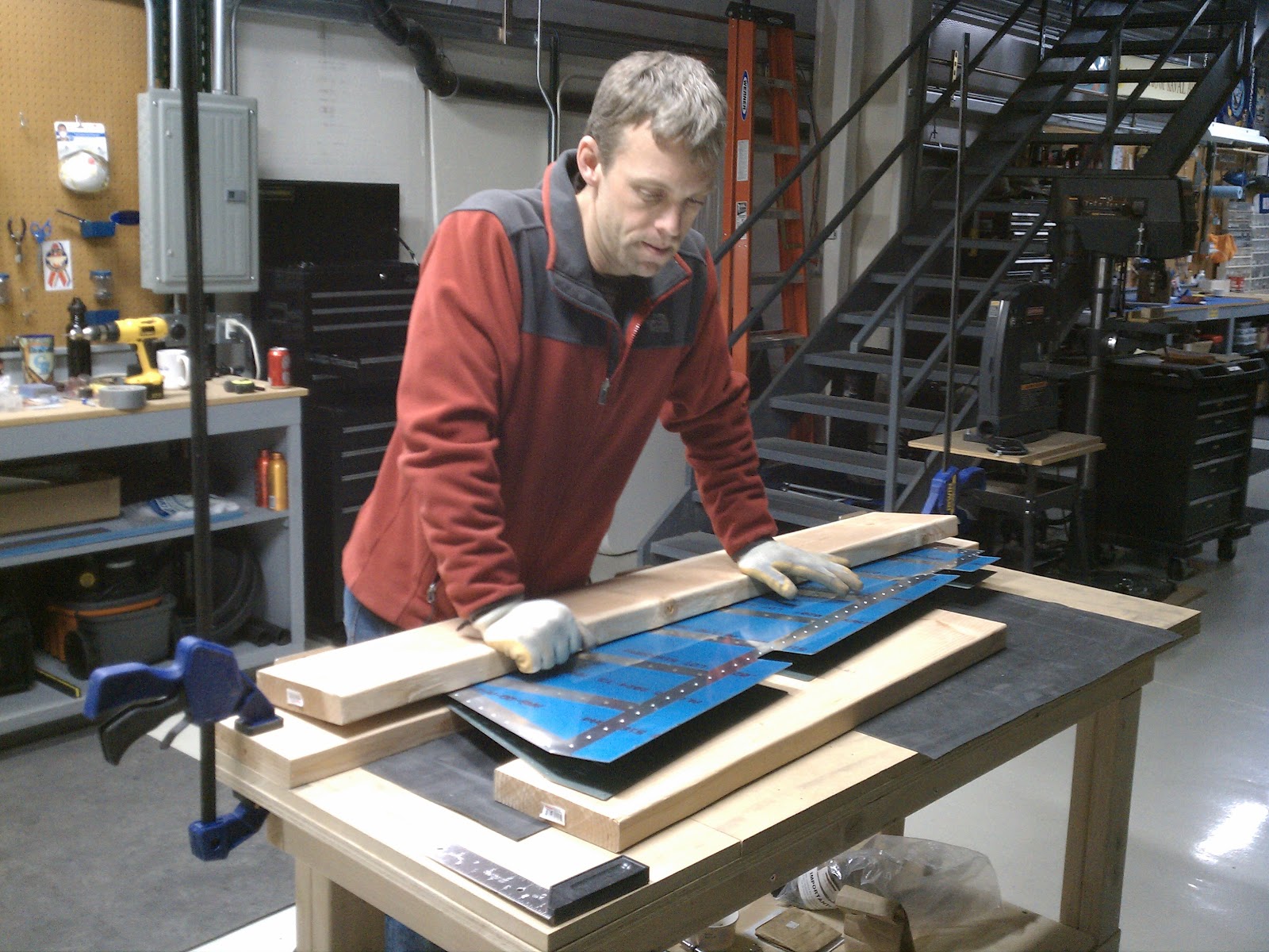
Bending the trailing edge is a bit unnerving the first time you do it.  You've put in a significant amount of time into the stiffeners and skin at this point, and the last thing you want to do is mess it all up.  I constructed a bending brake from a set of 2x8s connected at the back with evenly spaced door hinges.  I clamped the brake to the table top, and placed a 1/8" dowel in the trailing edge to prevent over bending.  It's surprising how much force it takes to complete the bend.  I made the first bend with the trailing edge close to the hinges, then slowly moved it out on following bends.  Soon, the skin was open just enough to sit on top of the spar when the skeleton is placed in the skin. This method worked well.

Bending trailing edge
Bend complete - straight edge sits flush to point where radius begins
Just a few rivets left, and the right elevator will be finished
Right elevator complete - yeah baby!